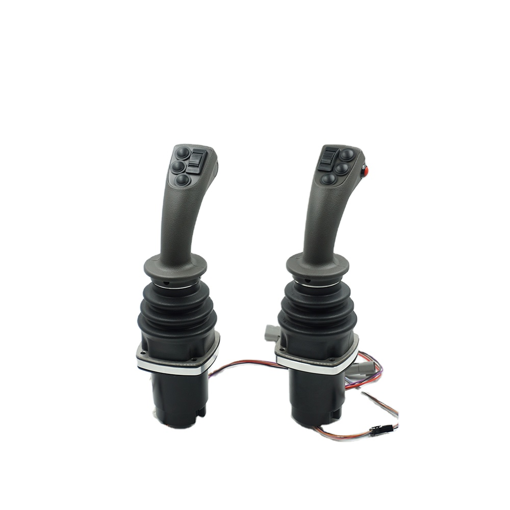
Product Features
• Heavy-duty industrial handles, supporting excavating machinery and equipment;
• Non-contact Hall sensor detection method;
• Spring return operation mode;
• There are many different types of grips for selection;
• Optional CAN bus output.
Application
This series of products are mainly used in heavy equipment ,like cranes, loaders, forklifts, excavators, aerial work platforms, tractors, harvesters, etc.

Technical information
Electrical parameters
Hall type
Power supply voltage | 5 ± 0.5Vdc |
Power supply current (rated power supply current) | <11mA (single axis) 22mA (dual axis) |
Limit allowable over voltage | 20Vdc |
Reverse limit allowable voltage | -10Vdc |
Linear error of output voltage | <± 0.2V |
Mechanical parameters
Rocking angle | ± 20 ° |
Mode of operation | Automatic spring return |
Starting force | 20N |
Maximum operating force | 11N |
Limiting force | > 300N |
Service life | > 2 million times |
Weight | About 660g |
Environmental parameters
Working temperature | -30C ~ + 70 ℃ |
Storage temperature | -40 ℃ ~ + 85 ℃ |
Protection grade | IP65 (above the installation panel) |
Product configuration
HJ89 series
Operation method
1A | Single-axis front-back operation |
2AC | Any operation direction of two axis |
Input voltage
S | 5Vdc (standard voltage) |
W | 9 ~ 36Vdc (wide voltage) |
Output signal
Hall type (supply voltage 5VDC)
H51 | Single Hall, 0.5 ~ 2.5 ~ 4.5Vdc voltage output |
H52 | Single Hall, 0 ~ 2.5 ~ 5Vdc voltage output |
H53 | Single Hall, 1.25 ~ 2.5 ~ 3.75Vdc voltage output |
J33 | CAN 2.0B bus output, source address is 33, J1939 protocol |
J34 | CAN 2.0B bus output, source address is 34, J1939 protocol |
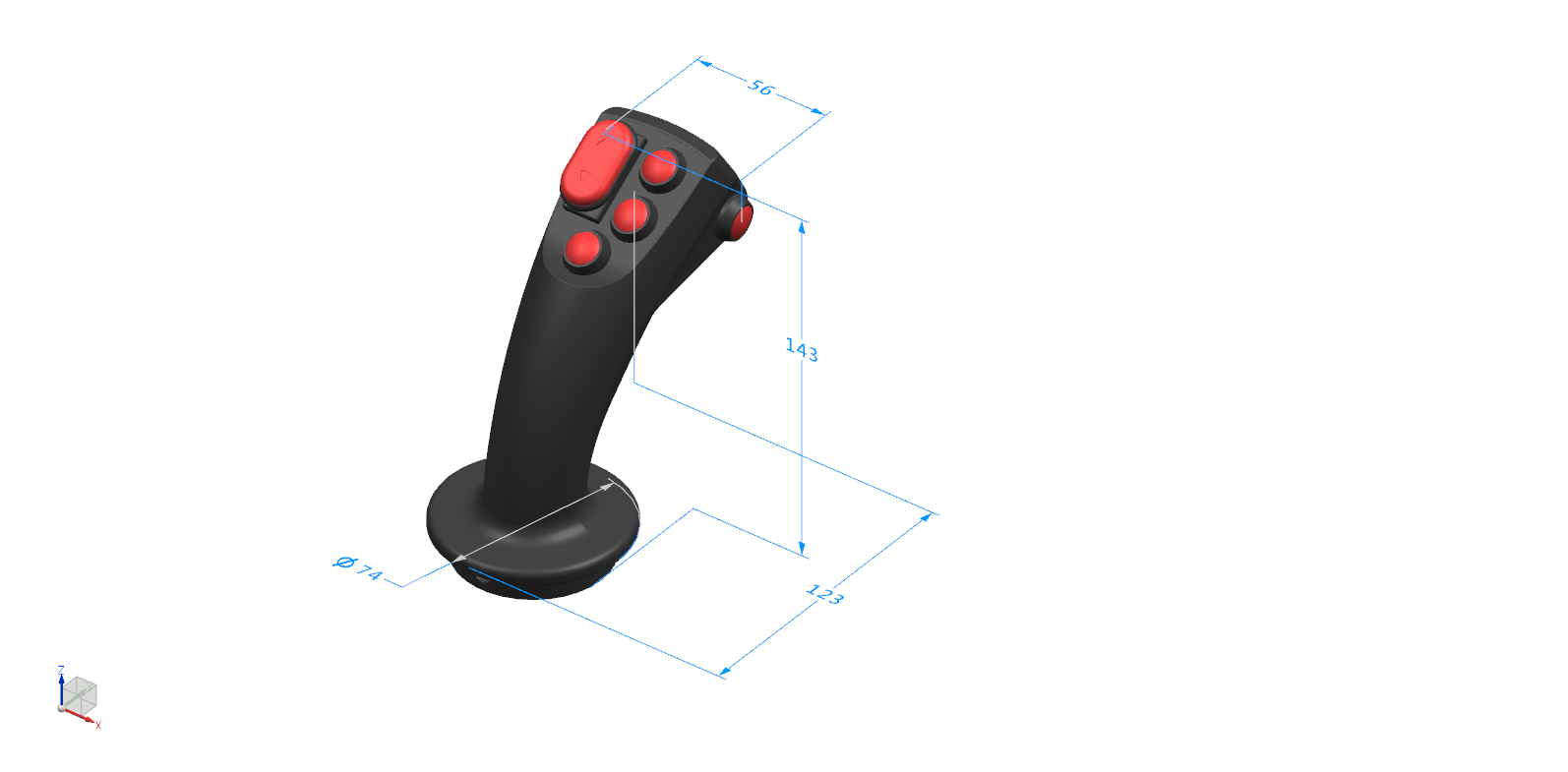
Grip of joystick
SP

Outgoing way
L (direct outlet)
D (Deutsch connector)
※ The outlet form of other connectors can be customized
Electrical Installations
CANbus output
Pin no | Function |
1 | Power 9~36v |
2 | Power 0V |
3 | CAN high |
4 | CAN low |
5 | CAN shield |
6 | N/A |
Hall sensor output definition
Color | Function |
Red | Power 5V input |
Black | GND |
Yellow | Hall output in front and rear direction |
White | Hall output in left and right direction |